Wednesday, August 12, 2020

Christmas in August

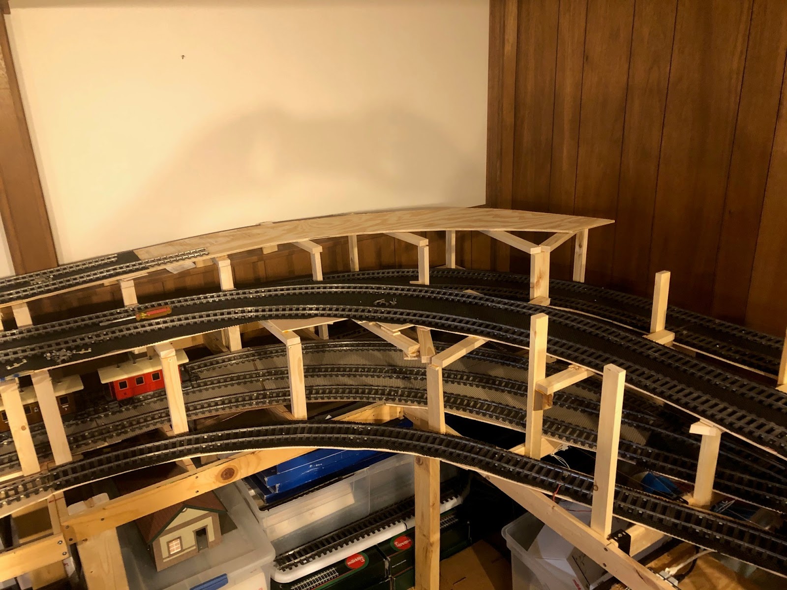
I read back through the blog a ways and must say I find it amazing how much has been accomplished on the layout this year.  What normally would have taken a few years has been completed in a matter of months.  The progress culminated last Saturday when, for the first time ever, I was able to run a train all the way around the layout.  What did I pick to commemorate this historic moment?  My gorgeous BR50 from KM1?  My MBW V200?  Maybe my very first 1-scale locomotive, the class 212 diesel-hydraulic?  Nope.  Without any fanfare, and to give me the best chance of success, it was my diminutive tank locomotive with a Maxi track cleaning car...

And successful it was, until the train approached the station.  I had forgotten that the curved turnouts from Huebner had polarized frogs, and without them being hooked up there was no power to the locomotive, so I had to attach feeder wires to those.  Since I'm only using one station track in each direction in the station right now I could get away without having to keep switching the polarization.  Anyway, after that was taken care of, it wasn't long before more and more trains found their way around the layout.  Not everything went as smooth as hoped.  The grades are very steep, and the F-Zug coaches are routinely ripping the couplers out of the sockets, breaking the tabs holding them in in the process.  I will need to come up with a more permanent coupler solution for those, I think.  But the train makes it up the grade and fits in the station!

By-and-large, the first few days of running have been a success.  I'm very happy to watch the trains traverse the different levels.  I still haven't watched enough to see where and when to expect a trains to appear next, i.e. what level and what track, so running trains is still a bit of a mystery.  

Still, I was able to run two trains at once, and at prototypical speed they take three to four minutes to traverse the layout once.  Here is a video of the parade section:


I think my favorite aspect of the layout is the broad curve of the station tracks on the top level.  It adds quite a bit of realism and elegance to that section, and I hope I can get the tracks lined up without kinks and parallel throughout the curve.  

Oh, and lastly, I figured out the short lead and stub siding to the 'north' end of the station, providing both a scenic element and some operational fun.  

There is still so much to do.  Hopefully I don't get distracted by being able to run trains, now...


Stay tuned!


Wednesday, July 29, 2020

And... ...We're back!

About a month after the last post I'm back at work on the layout.  Although I still don't have all the track I need to finish the main line I have enough to proceed with at least attempting to figure out the hardest part of the layout- the station.


The little device above will be instrumental in completing the station.  As mentioned in the previous post, I was going to need to bend a bunch of rails into radii that just don't exist.  The solution? Use Marklin's 5998 flex track kit and make them myself.  I had the track kits, but had no clue to what I was doing.  Step one was understanding how the track kits work.  Turns out they are easy to understand and very smart!  The only issue I had with the process was the rather unscientific way Marklin suggests bending the rails.  So instead I went in search of a rail bender, and discovered the beauty you see above, the Rail Ben 250 from Sunset Valley Railroad.  The Rail Ben 250 was designed for, as you can guess, code 250 rail, i.e. G-scale.  It takes a little practice, but the Rail Ben 250 works with Marklin 1-scale rail, which is actually code 200, I believe.  A little practice bending and unbending rails, and I was ready...


Those are the four station tracks at the 'north' end of the layout.  I laid them out provisionally this evening to see how they looked.  They look a little ridiculous going from the tight radii at the far end to the broad radii further down, but I'm hoping the signal tower, station, and a few well-placed trees help hide the tight curve as it comes out of the tunnel (yes, the plan is to have a tunnel at each end of the station).


About two-thirds of the station tracks are made of the gentle flex track.  The other third, towards the bottom, will be straight.  As soon as the remaining curves arrive (looks like I need two more to finish the main line) I can complete the track plan and be ready to finally run trains around the layout. 

More to come, hopefully soon!


Tuesday, June 23, 2020

FULL STOP

Well, this may be the last post for a while.  I have run out of track.  

"But Carsten, how can that be?"  Well, I'm glad you asked.  

It all has to do with the picture-a-day calendar someone on one of the Marklin Facebook groups posted back in January:


I admired this photo for a good long time, specifically how cool and realistic the gentle curve of the station looked.  I have decided that, instead of straight station tracks, I want to use some of the Marklin 1-scale flex tracks to build a gentle curve into the station.  I have some of those Marklin 5998 flex track building sets, but was planning on using them to build the final curves I need on the ends of both of the ramps coming up from the middle section.  So now I need more of the 1020mm and 1176mm radius curves.  And they are hard to find and damn expensive!

That's not to say there hasn't been any progress...
This is the section of the layout against the back wall.  The place where trains are parked is the three track staging yard on the lowest level.  What sits above it are the two opposing ramps leading up to the third/top/station level.  These two will loop around and connect in the station.  If you look to the right of this photo you will see...


...the track benchwork swinging around towards the front of the layout.  The track will come around another 45 degrees at the end of the benchwork before the station switches.  Note the lack of curves.  To complete the curved section on this side approaching the station I need 6 of the 1020mm and 1176mm curves.  Now, if you were to instead look to the left of the previous picture of the two ramps you would see...


...the track benchwork from the middle level swing up and around the curve here, too.  Again, I'm missing some pretty important curved track.  However on this, the 'north' end of the layout, you can see that I have proceeded further with the building of the track roadbed, and that benchwork, at least provisionally, continues all the way to the front of the layout, where...


... I have done some provisional laying of track at the entrance to the station.  The right-most tracks (the shorter ones in the image above that split from the right-most curved turnout) are the station tracks in one direction, and the two tracks next to it are the station tracks going in the other direction.  The track on the left that comes off the left-most curved turnout will go to a small yard, only two or three tracks.  This small yard will give me the ability to take manual control of a train or two to do some shunting in the yard versus just watching trains run around the layout.  

Note how the two tracks in the middle (the two 'left' station tracks) have a slight bend to them.  These are, in fact, built with the Marklin 5998 sets.  In both cases I started the three-foot long section of flex track with a tighter radius and then went to a broader radius for the gentle bend in the station.  

As soon as I get my hands on the needed curves I will post again, hopefully with pictures of the rest of the station with the gentle bend in it... 


Friday, May 22, 2020

It's always the one you least suspect...

I was finishing up the second level (yes, it's done) and it occurred to me that I hadn't even tested all the train cars to make sure I had sufficient clearance between the tracks and the risers for the tracks above.  Sure, I had grabbed my longest coaches, but what about all the different locos and other train cars with overhang?  And most important, what about my 'pride and joy', my KM-1 BR50 steam locomotive?  

I held my breath for each locomotive- the V200 from MBW, the BR50, the Shunting Crocodile, and the pair of V36's.  I ran the three-axle 'Umbauwagen' and my longest freight cars.  I breathed a sigh of relief- all seemed to clear the layout without any clearance or interference issues.  As I moved trains out of the lower staging yard for the next phase of construction, the whole operation turned into a disaster.

This guy.  This little Marklin Maxi baggage car started around the layout on the bottom level behind a Maxi locomotive and proceeded to HIT EVERY SUPPORT on the front side of the lower level.

If you look closely you can see why.  That little step under the baggage door sticks out further from the track than anything else in my entire rolling stock collection.  I halfheartedly considered grabbing my Dremel tool and making quick work of the offending steps, but after my conscience stepped in, followed by a string of obscenities, I went to work with both shaving off some material from the supports and repositioning the tracks.  Between the two, the baggage car now clears all the risers interference free.

So for anyone out there who is planning and/or building an elaborate layout in any scale, be sure you check clearances with every piece of rolling stock you have.  Because like me, you may discover that your worst enemy is the one you would never expect... 

x

Wednesday, April 29, 2020

On To the Second Level and Center Section

The answer to the question in my last post about getting the second level done before Easter is "Yes, sort of".  I did get the bottom level and a good chunk of the second level completed, but it may have taken slightly past Easter to achieve it.

The beige roadbed on the right side of the photo above is the formerly white foam from the previous post.  I gave it a light brown paint job which will form the basis of ballasting it.  This way if there is any sort of gap in the ballast you won't see bright white shining through!  


I have started to install the risers for the top level, where the station will be.  When I first started the layout I tried to be very careful about the height of the original benchwork because I wanted to make sure that the top level wasn't too high up (it's hard to visualize when you don't actually see anything other than an empty room).  I'm a little nervous that I may have gone too high.  We shall see once the station is in place!
  

And finally I added the benchwork for the middle of the layout.  Unfortunately it means I have to duck now when I go from one side of the layout to the other, but it was time.  This center benchwork is where the two returns for the ends of the dogbone, one on the bottom and one on the middle level, are located.  As you can see in the picture above I have already installed supports and provisionally laid the track in the middle.  Also, in the foreground  of the photo you can see the two-track staging yard for the middle level on the left coming together via the switch in the foreground. EDIT: It occurs to me that the track plan shows that the staging yard for the middle level was supposed to be on the other side of the layout, above the lower staging yard.  I discovered that I needed a little too much space over there, and that it made more sense to have the staging yard tracks on the opposite side.  So a train coming from the station will enter the second level on the track on the inside of the second level (the track directly above the switch in the foreground), go across the middle via the upper return, swing around to the left in the back where the two-track staging yard starts, and then come down the left side, around the bottom / foreground, and back up to the station.  The idea is to have one train coming into the staging yard and the train on the other track going out.  This mixes up the traffic in the station a little.  

Next up is finishing the center section and the return loops, and adding the benchwork to make it up to the top level of the layout!

Wednesday, April 8, 2020

The Upside (if there is one) to COVID-19

I took a look at the January 23 post to see what progress had been made on the layout just over two months ago.  What would normally take years has been completed in a matter of weeks.  Without further ado...

I took my test oval apart (leaving the staging yard in place, of course) and began the bottom level main line.  I chose to leave off the 'return' on the dog bone that cuts through the middle of the layout so I wouldn't be restricting my access to the area in the interior of the layout, or have to duck and crawl under that center section all the time.  My plan is to leave that open as long as possible, likely until the bottom and middle layers have been built, and only installing it before adding the station on the top level.  The first step was to build the incline out of the bottom level and through the parade section on the middle level.  

The incline from the bottom level to the middle level has no tracks underneath it, so I could use some 1x10 plywood to build risers for the track.  Note the clamps on the risers- I switched from screws to glue to hold everything together.


The image above shows the same section (in the background) as the picture above it with plywood and shelf liner added.  I also have the curve on the right side of the layout done, coming up from the bottom level.

Next up is the parade section, which requires realistic track ballasting and scenery.  I used an old trick from the original Carstenbahn One using Styrofoam and a hot knife to form the roadbed.


The rectangular foam sheets get glued to the plywood roadbed and are carved to fit using the hot knife. 

  
Before carving the embankment it's important to place the track in its final position.  I have to make sure there is enough clearance between the tracks.  My passenger cars have the biggest overhang so I use a pair of those for clearance testing.   Although I used the Marklin 1-gauge flex track kits to have a gentle curve transitioning to the straight section of the parade line, I did have to use the 'swine radius' for part of the curve.  

Once the track was properly positioned, I use a self-bent wire in the hot knife to carve the edges of the roadbed.


And there is the result before painting and ballasting.  The flex track looks really nice,  Had I known how good this would look (and how short the parade section would be) I would have made the curve longer!


I have continued to build the roadbed on the second level.  The curved sections are particularly difficult to support.  In addition, I discovered that by putting the tracks on the lower level all the way to the edge of the layout I didn't leave a spot for the supports for the levels above it.  

My trio of clearance testers!

So that's where we are now.  The bottom level is done except for the wiring of the reed switches and the track switches, and the middle level has been started.

Now, can I get the middle level done before Easter?


Monday, February 17, 2020

I used to hate wiring...


So yes, I used to really hate wiring.  I don't hate it nearly as much anymore, thanks to a wiring system that was introduced to me by Tim Eckert, fellow Marklinist, over twenty years ago...

The concept is simple: instead of having wires running around the layout with occasional distributors to feed the track and accessories, the electrical bus is made up of several runs of bare copper wire that circle the layout, allowing hook-up anywhere a wire drops from above.  The bus can be created using any number of copper wire runs.  I chose four in total, which provide the following:


Brown:  accessory and track ground
Red: track power
Yellow: accessory power
White:  feedback ground


Most of you are familiar with the first three, as they are identical to the connectors on a typical Marklin (or other train) transformer.  The last one, the white feedback ground/return, is designed to reduce the wiring to the reed switches.  You see, the way my feedbacks work is that the reed switch closes when a magnet passes over it, completing the circuit back to the S-88-style module to 'sense' the location of a train.  I'm able to tie all the wires on one side together into the bus and only need to come back with one wire.  Here is a visual representation using the feedback modules from Digikeijs:
See how the light-brown wire connects all the common terminals together?  That's why I added another bus wire.  Of course, I'm using reed switches while the image above shows using Marklin HO track to close the circuit, but the principle is the same.

Anyway, back to my bus wires.  Here is how things look from above the layout looking down through the benchwork:
I added small tabs of colored electrical tape about every three feet all the way around the layout to reduce the chance that I hook things up wrong.  The rolls of colored tape are readily available at most home stores, and even at my local Ace Hardware.

I originally considered drilling holes in the benchwork for running the bus wires, but ended up using eyelets instead:
Two things to note in the image above:  First, the eyelets are positioned on every other piece of benchwork.  I realized it was fairly pointless to put them on every single span, as long as the wire is fairly taught (but not too taught, as it is copper and will stretch over time).  The other thing you'll notice is an extra eyelet to the left (in the image above) of the eyelets with the bus wires running through them.  This eyelet appears on every span of the benchwork.  It will be used for those wires that drop down from the layout overhead and run to either a feedback module or an accessory decoder.  Each switch will have two wires, while uncouplers or reed switches will have one wire to run. 

Here's a final picture from underneath the staging yard on the lowest level.  Even in the dark it's easy to identify the bus wires by color.  Still, I plan to have lighting underneath the layout for easy troubleshooting...
A couple of comments:  First, make sure you space your wires fairly far apart, I'd say a minimum of 4 inches.  This is so you can get a wire attached to one bus wire without pushing on the one next to it.  More importantly, when you turn a corner you need to be careful to maintain the space between the wires.  In fact, it would be good to have an intermediate diagonal brace with a set of eyelets on it.  The image below shows why corners tend to be tricky:
The brown rectangles represent cross spans of benchwork with either through-holes or eyelets underneath.  The three colored lines represent three wires of the electrical bus.  See how close those wires get together when you have a sharp bend and a fair distance from the two perpendicular benchwork pieces / eyelet sets?  If the wires are insulated that's not a problem, but with bare copper wire this is just asking for an electrical short...

If you choose to solder your wires to the bus you'll also need some room for your soldering iron and the solder, another reason to space your bus wires fairly far apart.  And this buggest from personal experience: If you are soldering, have a good, hot soldering iron.  You'll probably find yourself bending over the layout or crouching underneath to solder wires to the bus, so the sooner you can get the bus and connecting wire hot enough to solder, the better it will be on your joints and back!  I'm actually going to try to not solder my wires to the bus, but rather to use liquid insulation for maintaining the connection.  But more about that in a future post...

It may be a couple of weeks before we tackle the next stage of the layout, which is the roadbed for the track to go from the bottom level of the layout to the middle level.  This will give us a very clear understanding of what challenges the grade will cause...