Wednesday, April 8, 2020

The Upside (if there is one) to COVID-19

I took a look at the January 23 post to see what progress had been made on the layout just over two months ago.  What would normally take years has been completed in a matter of weeks.  Without further ado...

I took my test oval apart (leaving the staging yard in place, of course) and began the bottom level main line.  I chose to leave off the 'return' on the dog bone that cuts through the middle of the layout so I wouldn't be restricting my access to the area in the interior of the layout, or have to duck and crawl under that center section all the time.  My plan is to leave that open as long as possible, likely until the bottom and middle layers have been built, and only installing it before adding the station on the top level.  The first step was to build the incline out of the bottom level and through the parade section on the middle level.  

The incline from the bottom level to the middle level has no tracks underneath it, so I could use some 1x10 plywood to build risers for the track.  Note the clamps on the risers- I switched from screws to glue to hold everything together.


The image above shows the same section (in the background) as the picture above it with plywood and shelf liner added.  I also have the curve on the right side of the layout done, coming up from the bottom level.

Next up is the parade section, which requires realistic track ballasting and scenery.  I used an old trick from the original Carstenbahn One using Styrofoam and a hot knife to form the roadbed.


The rectangular foam sheets get glued to the plywood roadbed and are carved to fit using the hot knife. 

  
Before carving the embankment it's important to place the track in its final position.  I have to make sure there is enough clearance between the tracks.  My passenger cars have the biggest overhang so I use a pair of those for clearance testing.   Although I used the Marklin 1-gauge flex track kits to have a gentle curve transitioning to the straight section of the parade line, I did have to use the 'swine radius' for part of the curve.  

Once the track was properly positioned, I use a self-bent wire in the hot knife to carve the edges of the roadbed.


And there is the result before painting and ballasting.  The flex track looks really nice,  Had I known how good this would look (and how short the parade section would be) I would have made the curve longer!


I have continued to build the roadbed on the second level.  The curved sections are particularly difficult to support.  In addition, I discovered that by putting the tracks on the lower level all the way to the edge of the layout I didn't leave a spot for the supports for the levels above it.  

My trio of clearance testers!

So that's where we are now.  The bottom level is done except for the wiring of the reed switches and the track switches, and the middle level has been started.

Now, can I get the middle level done before Easter?


Monday, February 17, 2020

I used to hate wiring...


So yes, I used to really hate wiring.  I don't hate it nearly as much anymore, thanks to a wiring system that was introduced to me by Tim Eckert, fellow Marklinist, over twenty years ago...

The concept is simple: instead of having wires running around the layout with occasional distributors to feed the track and accessories, the electrical bus is made up of several runs of bare copper wire that circle the layout, allowing hook-up anywhere a wire drops from above.  The bus can be created using any number of copper wire runs.  I chose four in total, which provide the following:


Brown:  accessory and track ground
Red: track power
Yellow: accessory power
White:  feedback ground


Most of you are familiar with the first three, as they are identical to the connectors on a typical Marklin (or other train) transformer.  The last one, the white feedback ground/return, is designed to reduce the wiring to the reed switches.  You see, the way my feedbacks work is that the reed switch closes when a magnet passes over it, completing the circuit back to the S-88-style module to 'sense' the location of a train.  I'm able to tie all the wires on one side together into the bus and only need to come back with one wire.  Here is a visual representation using the feedback modules from Digikeijs:
See how the light-brown wire connects all the common terminals together?  That's why I added another bus wire.  Of course, I'm using reed switches while the image above shows using Marklin HO track to close the circuit, but the principle is the same.

Anyway, back to my bus wires.  Here is how things look from above the layout looking down through the benchwork:
I added small tabs of colored electrical tape about every three feet all the way around the layout to reduce the chance that I hook things up wrong.  The rolls of colored tape are readily available at most home stores, and even at my local Ace Hardware.

I originally considered drilling holes in the benchwork for running the bus wires, but ended up using eyelets instead:
Two things to note in the image above:  First, the eyelets are positioned on every other piece of benchwork.  I realized it was fairly pointless to put them on every single span, as long as the wire is fairly taught (but not too taught, as it is copper and will stretch over time).  The other thing you'll notice is an extra eyelet to the left (in the image above) of the eyelets with the bus wires running through them.  This eyelet appears on every span of the benchwork.  It will be used for those wires that drop down from the layout overhead and run to either a feedback module or an accessory decoder.  Each switch will have two wires, while uncouplers or reed switches will have one wire to run. 

Here's a final picture from underneath the staging yard on the lowest level.  Even in the dark it's easy to identify the bus wires by color.  Still, I plan to have lighting underneath the layout for easy troubleshooting...
A couple of comments:  First, make sure you space your wires fairly far apart, I'd say a minimum of 4 inches.  This is so you can get a wire attached to one bus wire without pushing on the one next to it.  More importantly, when you turn a corner you need to be careful to maintain the space between the wires.  In fact, it would be good to have an intermediate diagonal brace with a set of eyelets on it.  The image below shows why corners tend to be tricky:
The brown rectangles represent cross spans of benchwork with either through-holes or eyelets underneath.  The three colored lines represent three wires of the electrical bus.  See how close those wires get together when you have a sharp bend and a fair distance from the two perpendicular benchwork pieces / eyelet sets?  If the wires are insulated that's not a problem, but with bare copper wire this is just asking for an electrical short...

If you choose to solder your wires to the bus you'll also need some room for your soldering iron and the solder, another reason to space your bus wires fairly far apart.  And this buggest from personal experience: If you are soldering, have a good, hot soldering iron.  You'll probably find yourself bending over the layout or crouching underneath to solder wires to the bus, so the sooner you can get the bus and connecting wire hot enough to solder, the better it will be on your joints and back!  I'm actually going to try to not solder my wires to the bus, but rather to use liquid insulation for maintaining the connection.  But more about that in a future post...

It may be a couple of weeks before we tackle the next stage of the layout, which is the roadbed for the track to go from the bottom level of the layout to the middle level.  This will give us a very clear understanding of what challenges the grade will cause...


Monday, January 27, 2020

The Track Plan

Greetings, everyone!  It occurs to me that I haven't ever published the track plan.  I designed the whole layout using Winrail, a software I have used for decades.  The layout is a dogbone design, meaning it's a double-track railway line with loops at each end.  In my case, the loops are one and two levels below the station, so it's what is known as a folded dogbone layout.  I also have staging yards on each loop level, allowing me to switch off trains and provide some variance in what runs around the layout.  Let's go through the levels one-by-one...

Bottom level:  

This is the section I'm currently working on.  The three-track staging yard in the upper section of the layout plan above is completed.  Trains enter the staging yard from the right and exit to the left.  Then they make a half-circle before looping back towards the top of the track plan, completing the dog bone end.  The main line proceeds around the circumference of the bottom level while gaining height in a 2% grade.  By the time it comes past the front of the layout again (the area in yellow) it is at the same height as the middle level.  The area shown in yellow is actually the only part of the track plan here that will be in view.  It is the 'Paradestrecke' or 'parade line' and, although the track plan shows it mainly straight, will be built using Marklin's you-build-it flex track.

Now for the middle level:

This level sits about 20 cm above the lower level.  Because it has to fit inside the tracks coming up from the lower level and the tracks coming down from the upper level, the staging yard is smaller- only two tracks.  Still, it will allow one train to come in and another to go out, providing some variety to the train traffic in the station.  This entire end of the dogbone is located out of view of the spectator.  

Top level:

Here is the train station, located on the top level.  The track plan for the station is provisional- I'll decide exactly how I want the station to look and whether I want to add some stub sidings for freight cars, additional passing sidings in the station, etc.  Again, the station itself will be visible, but the track will come out of a tunnel and disappear into a tunnel at both ends.  Because of the use of  unrealistic 1020mm (the so-called 'Schweineradius' or 'swine radius') and 1176mm curves I have designed the scenery to hide those curves as much as possible.  As you can guess, 'A' connects to 'A' and 'B' connects to 'B' on the other levels.  The grade down to the lowest level is mostly 2% and the grade down to the middle level is about 3%.  

The single biggest comment I can make regarding track plans is this: Don't be afraid of multiple levels.  It allows for so much more in a limited space than a single level does.  I strongly recommend, however, that you actually lay out some track before construction to see how tracks on multiple levels interact.  I did this when designing this layout and discovered a few places where tracks didn't have enough clearance from the level above.  This is why the middle level is narrower than the lower level.  In the original design the middle and lower levels were identical, but when I laid out the tracks I discovered the interference issues.  

Thursday, January 23, 2020

Laying the first track and firing up the laptop....

I think that, had I made it a New Year's Resolution, "playing more with trains" is a resolution I could have kept!  There has been significant work done on the layout in the past couple of months.
The three-track staging yard on the lower level was completed.  I cut wood to sit under the tracks on the benchwork instead of just leaving the whole top covered with plywood.  Why?  First, the cross-braces of the table frame will serve as supports for the risers and track as it ascends / descends from the upper levels.  Also, by only putting wood under the tracks, it allows me to reach tracks from under the layout that would otherwise be impossible to access.  Finally it allows light to shine up from underneath the layout for troubleshooting.  I unboxed several of my F-Zug passenger cars to use for clearance testing as I laid out the track.  This is a very important step, and I encourage everyone to find your cars with the longest distance between wheels and those with the longest overhang in front of wheels.  Then run them on each track next to each other, moving them by hand to test every possible interaction.  It took me a long time to work out the placement of all three tracks to insure minimal interference between cars.  I got about 90% there, and have my fingers crossed that I won't regret that last 10%...  Anyway, here is how the staging yard looks now that it has been completed:


You'll notice in the picture above that there is something between the track and the plywood.  It's actually shelf liner designed for work benches.  It's available at Lowe's and Home Depot for those of you in the states.  This is not the paper shelf liner for the kitchen, but a foam-like liner a couple of millimeters thick.  It isn't cheap, but it does a very nice job of sound deadening.  I had a loop of track with half on the mateiral and half just on the wood, and the difference was noticeable.  I don't plan to put it under the track that will be visible, but for the hidden areas and staging yards it will help keep the noise down.  

Observant visitors may notice there is something else between the ties in the image above.  They are cylindrical reed switches, installed to allow automation of the layout once it's finished.  I purchased thirty of them and am already convinced that I will need more.  Here is a close-up of how they look in the track:


Each track in the staging yard has three such sensors to identify the beginning, middle, and end of the siding.  The Carstenbahn One track plan will have the main line broken into a series of blocks to allow the operation of multiple trains on the same line, and each block will have at least two such sensors.  They are set at the same height as the top of the rails, and I have placed magnets on the bottom of the locomotives using double-sided adhesive foam pads from 3M.  My testing has found that the reed switches are very reliable even when locomotives pass at high speed.  This will be my solution for detection throughout the layout when I add computer control.
  
So far my relationship with computer control has been love/hate.  I spent several weekends working with iTrain, a very sophisticated piece of software that had some nifty features at a very affordable price point.  Unfortunately I got very frustrated with the manual (the software comes from Holland and the manual was translated into English) trying to set up a very basic control of the staging yard and the loop of track.  I abandoned it mid-January and switched to TrainController by Railroad & Co.  This software is much more expensive for what I want to be able to do, and I think the resulting switchboard is much less attractive than the iTrain one, but it only took me a day to do everything I wanted to accomplish and more.  Not only was I able to have the trains pull out of the staging yard sequentially and take a trip around the loop, but I was also able to make the passenger trains stop at the 'station' for 10 seconds before proceeding while the freight train passed right through without stopping.  Plus the manual was much easier to understand.  Still, my experience is anecdotal.  I encourage anyone who is looking at train control software to consider your options carefully and do your research before committing to one or the other.  

The next step is to pull all the plywood sheets off the table tops and begin adding track up to the next level...   


Tuesday, November 19, 2019

Four Years...

Well, it has been four years since I last posted.  However that's not to say there hasn't been activity.  It started with the Ramcke family moving into a new house.  We're now downriver, in a small house located wonderfully close to an active railway line.  In fact, here is a sample of what I get to enjoy pretty much every day when I walk the dog:


"But Carsten," you say, "What has become of Carstenbahn One?"  Well, that's a good question.  Turns out I'm not the only one who moved.  My parents have also moved, and to Florida.  The condo in Auburn Hills is sold, and as you can imagine, the Carstenbahn One layout is no more.  On the bright side, the new house has a fully-finished basement, and there is a good spot for a modest 1-scale layout.  You would think that, after four years, there would be a bunch of progress and I'd be able to show off pictures of trains running around a layout in similar condition to the Carstenbahn One layout in my parents' basement (after all, that was four years, too).  Well, actually the space was a basement for our daughter for a couple of years, so I have only recently begun to build.  However I'm pleased to provide some progress and share some information on the new layout.

First, a picture of the available space, roughly 21 feet x 18 feet:

See that table in the back?  That's actually one of the frames from the original layout.  Although the space is significantly smaller, I used all the benchwork in the new space.  I built the new layout's benchwork using two 3x6-foot sections for every 6 feet of the new layout.  One 6-foot section to be used for stabilization and storage, and the other as the actual layout benchwork:

The bottom then gets covered by a sheet of plywood and acts as a storage shelf for boxes, tools, stored trains, etc, while the top contains the actual track (the entire layout will be built using an open benchwork concept). 

I designed a pretty optimistic track plan, in that it is a triple-level dogbone main line, with a station on the top level featuring two passing sidings, a small yard and a branch line three-track station staging yard.  The first level down from there is a two-track staging yard and one of the dogbone returns, along with a parade section that goes down to the bottom level, which is the other end of the dogbone and a three-track staging yard. 

I laid out the tracks on the tables, at least for the two staging yards, to see how everything would fit:

The post-it notes in the image above show the necessary elevations for each section of track.  I was surprised to find that I could go with a reasonable 4% grade on most sections of the layout, with 5% necessary in just a few places, and always on straight sections.

Finally, here are a few more images of the benchwork with the tracks provisionally laid out.  First, the raw layout:

Next the three-track staging yard on the bottom level.  The diagonal track that represents the 'return' of the dogbone is not laid out, as it crosses the center of the layout.  The two tracks on the outside of the staging yard (on the far right) represent the ascending tracks from the staging yard to the intermediate level parade line and top level station. 

In the image below you can see a curved track ending at the edge of the table near the top-center of the photo.  This is the return of the bottom level of the dogbone.  That track, and the one at the start of the staging yard (not visible) make up the two tracks on the inside of the left side of the benchwork in the image below.  That one 'lone' track on the outside left side is one of the two that will make up the parade line, which is actually the next loop of the two tracks next to it. 

Finally here is a view of the benchwork where the bottom-level staging yard sits.  Note the cut in the benchwork at the top of the image to allow access to the egress window:
I know the explanations above are confusing, but will try and post the actual three-level track plan in the next blog entry.

More to come, hopefully soon!


Saturday, January 2, 2016

2016 Resolution: More Fun with 1 Scale!

Happy New Year, everyone!  It has been a while since I last posted.  I'm hoping I can spend more time with 1-scale in 2016 and provide more information here in my blog than I have the last couple of years.  Luckily the past few weeks have been active for me in the King's Gauge, thanks largely to a package from Lokshop containing some Loksound L decoders I'd like to use for upgrading my old Marklin locomotives, largely thanks to the new ESU magnets.  But I'm getting ahead of myself.

Many of us 1-scalers have older models with the AC motor that aren't very conducive to upgrading to digital.  That has changed thanks to ESU's production of the 51965 magnet, a permanent magnet to replace the field winding on the older Marklin motors.  What it does, in fact, is turn the AC motor into a DC motor, which then allows us to add a decoder and have a modern digital locomotive with all the bells and whistles (pun intended) of their contemporary counterparts.  I have two such locos, a BR80 steam loco and a DHG 400.  The BR80 will be getting synchronized smoke along with sound, and since that's a more involved process I'm going to start with the DHG diesel, which is getting a digital upgrade with sound only (okay, and maybe some fancy lighting upgrades, too).  Here is a picture of our candidate:

Below is a picture of the inside of the locomotive after the three screws holding the body on are removed.  There is some wiring that have done but no worries.  Everything is coming out- the reversing mechanism, the motor, etc.  Now is a good time to lubricate the gears, too...


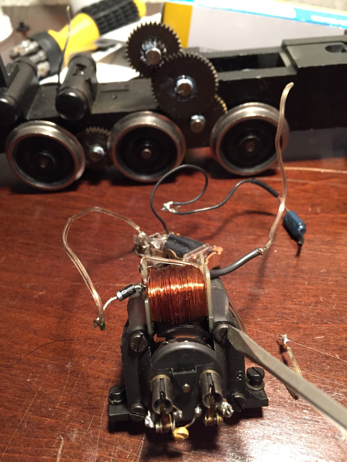
The first step of the upgrade is to replace the field winding with the new permanent magnet by removing the four screws and taking the motor apart.  You'll need a nut driver to hold the 5mm nut while you turn the slotted screw (the four screws are visible in the image below with my screwdriver on one of them).  Frankly, for me that was the toughest part of the job, as I was using a 7/32 nut driver, which is juuust about the right size, and Marklin has made sure those nuts are on TIGHT...

 Below is a picture of the three pieces of the motor (and the brushes) once the four screws are removed.  In the background you can see the packaging for the ESU 51965 permanent magnet.  It's really a simple swap from here- take the old center section out, replace with the new magnet, and you are ready to reinstall your new (DC) motor.

Here is how everything looks when the motor is reinstalled with the permanent magnet.  Note the lack of coil and wires.  Don't forget to snip off the noise suppression diode between the motor poles, which is still partly visible in the picture below.  Compare this picture to the image of the motor two pictures above- what a difference, eh?  There are now only TWO wires connected to the motor and the whole reversing solenoid mechanism is gone.  Plenty of room for a decoder, speaker, and even some additional modifications...

Last picture for today:  I hooked up leads from the chassis and wheel pickups to the two sides of the motor and test-ran the locomotive using DC power.  It ran flawlessly.  Next I will install the decoder with sound, and maybe add a few other special upgrades...

More to come!  

Tuesday, July 7, 2015

Out With the Old, In With the New...

In a previous post I talked about finally replacing my Marklin V200 which I had to sell many years ago due to a financial crisis.  When I purchased the 'new' Marklin V200 I have to admit that I was a little disappointed.  Although the technology of digital operation and detail level on models has come a long way in the decade or so since I first purchased the V200, I was surprised at how little Marklin had upgraded on the re-release of their V200.  The headlights were the same yellow LEDs as before, the sound functions were only modestly expanded, and the model had changed little in terms of detail.

Well, it turns out that an O-scale manufacturer in Germany has begun 'dabbling' in the King's Gauge.  Modellbahn Werkstatt, or MBW for short (http://mbw-1zu32.de/) released the V200.1 about six months ago.  The price was very reasonable, and a sale on remaining inventory last month encouraged me to place an order.  By selling my Marklin V200 on eBay I had enough money to order the MBW model complete with a Loksound XL 4.0 decoder.  Anyway, enough text.  Here are some pictures of the new model:


I particularly like the design of the V200.1 versus the Marklin prototype because of the 'beefier' nose of the locomotive.  


In the photo above you'll notice the new signal tower, which I will blog about in the upcoming weeks.


The new V200.1 makes a good impression in front of my FD train.  


Overall I'm very happy with the model.  The detail is significantly better, the sounds are more realistic, and the functions and features of its digital operation are a step above the Marklin model.  My only complaints are that the model lacks an engineer in the cab and that from a sound standpoint the bass that the Marklin model had, that throaty rumble that a diesel locomotive should have, is missing on this model.  Perhaps a speaker swap or enclosure design is in the future.